LELEK

LELEK / Electronics

Board v7, v8

A button, a battery, a sound module.

Eight board versions got the circuit from 13 parts and a microcontroller down to a button in the power line. Hold it and the bird sings; let go and it stops.

The circuit

It works because nothing is on when you are not pressing.

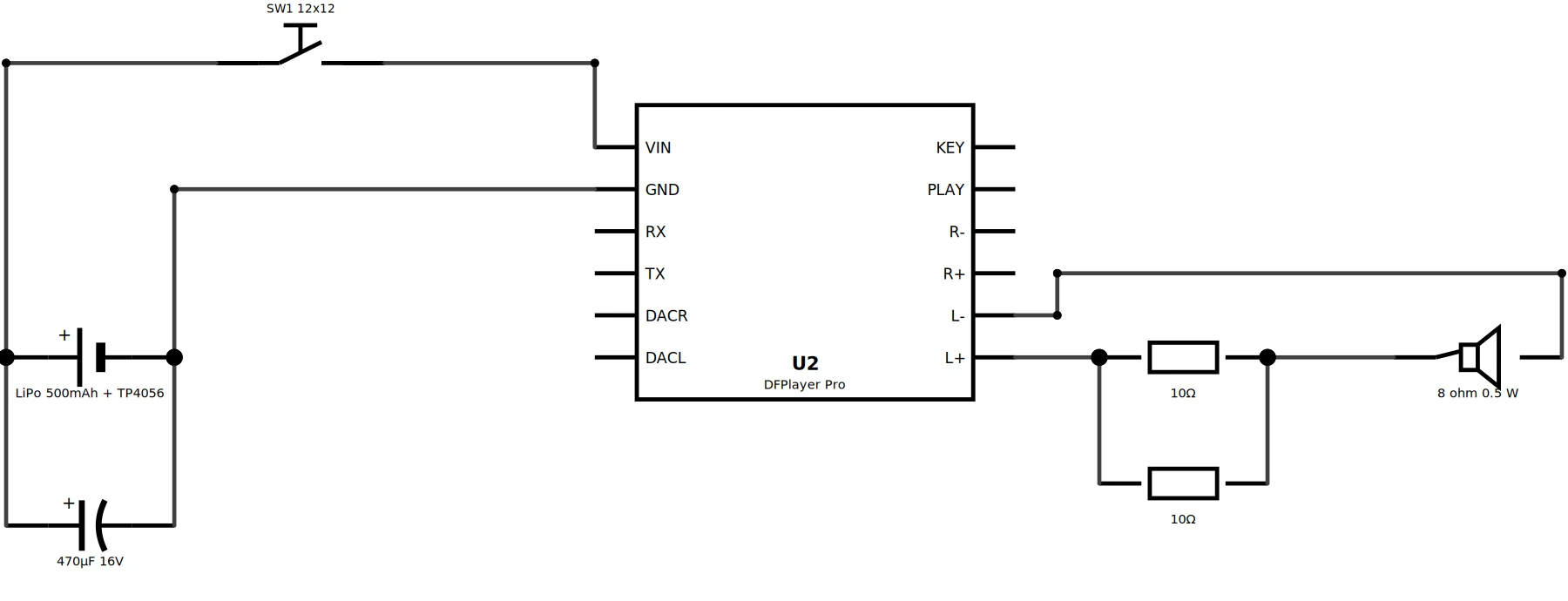
  • The button sits in the battery line. While it is held, the LiPo (through the charger module's output) powers the DFPlayer Pro, which starts playing as soon as it gets power.
  • When the button is released the module has no power, so nothing drains the cell between presses.
  • C1, 470 µF, sits across the battery, before the button, and supplies the amplifier's current peaks.
  • The speaker sits on the module's L+ and L− amplifier output through R1 ∥ R2, 5 Ω in total.

Board 89.4 x 27.9 mm, two layers. Same outline from v4 to v8, so the enclosure never had to change.

Schematic of board v7
Schematic, v7. Battery, button, DFPlayer Pro, the 5 Ω resistor pair and the speaker.

Schematic, breadboard, PCB

Three views of version 7.

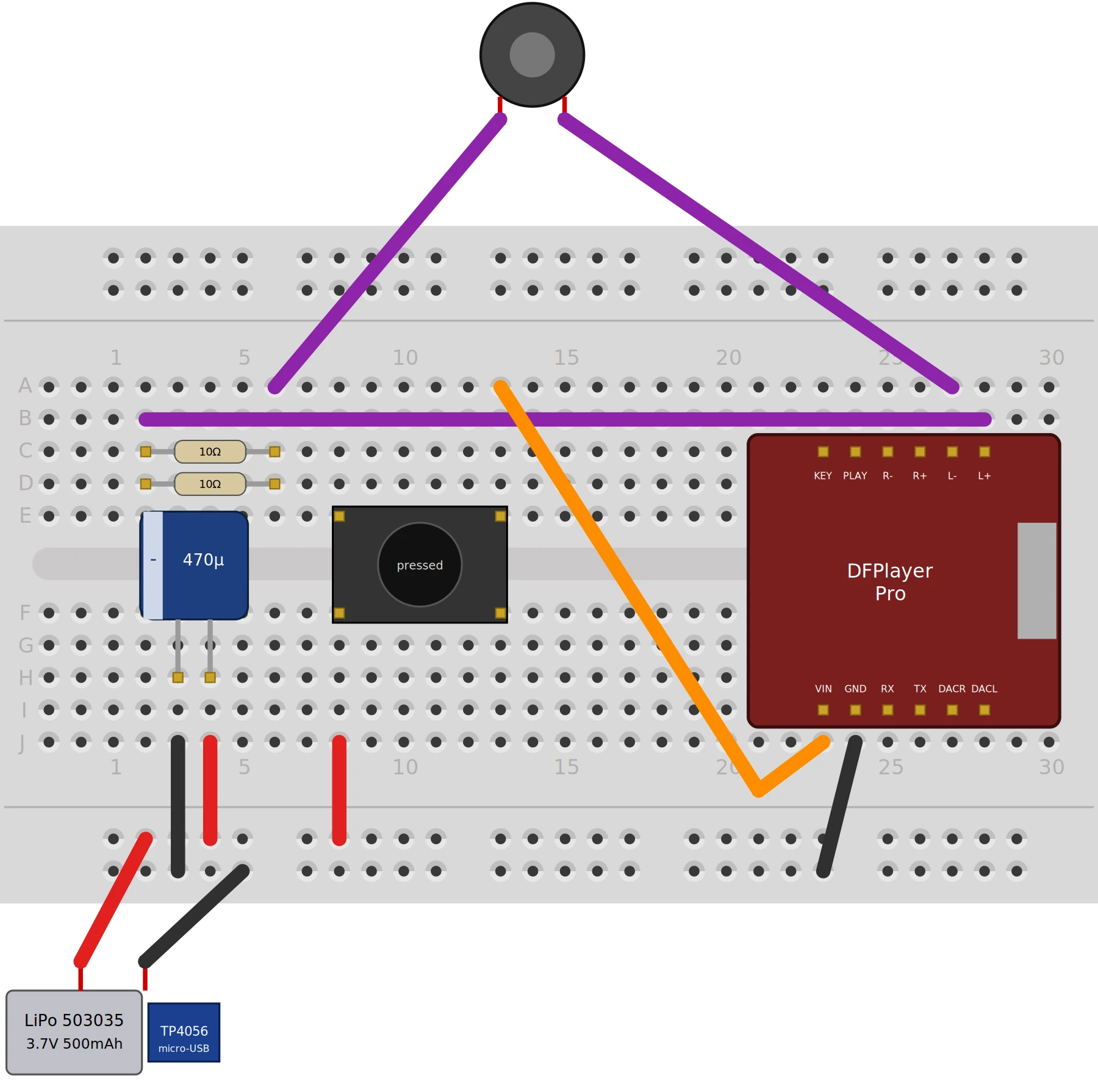
The boards are generated by scripts and checked by independent ones, not drawn by hand. The breadboard and the schematic are compared net by net (6 nets each), and the exported Gerbers are compared against the schematic netlist.

Breadboard view of the v7 circuit on a half breadboard
Breadboard. Every part has a SPICE model, so Simulate works: with the button pressed the player gets 3.69 V, 0.5 V falls across the resistors and 0.8 V across the speaker.
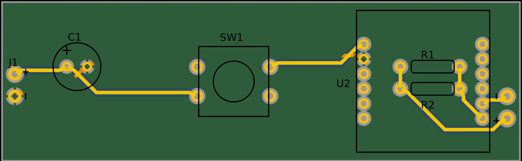
PCB layout of v7, 89.4 by 27.9 millimetres
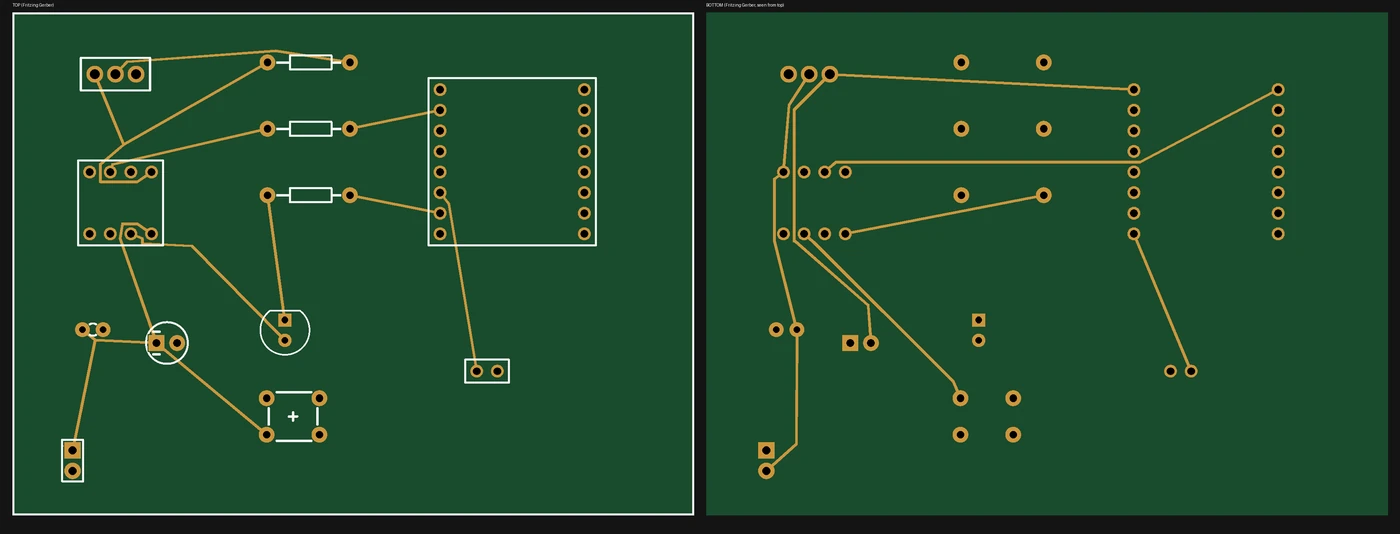
PCB, v7. J1 battery, C1, the 12 x 12 mm button in the centre, the DFPlayer Pro at the chest end with R1 and R2 under it.
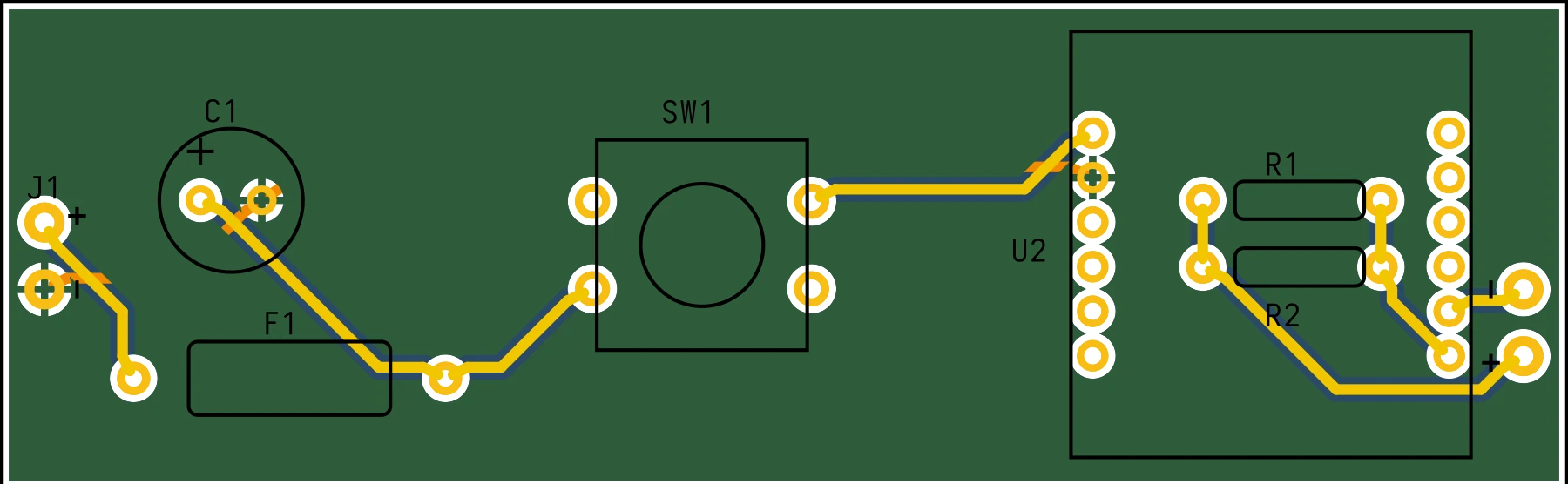
PCB layout of v8, with a thermal fuse added in the battery line
PCB, v8. The same board with a 77 °C thermal fuse below the J1 / C1 row.

Design choices

Three small additions made cheaper parts safe.

Moving from TME to Slovak and Czech shops cut the price, but the cheaper cell and speaker needed help.

C1: 470 µF across the battery

The 503035 cell is rated for 0.25 A maximum discharge, less than the player and amplifier can draw on loud peaks. C1 supplies those peaks so the cell voltage does not dip. It sits on the battery side of the button so a press never dumps a charged capacitor through the switch contacts.

R1 ∥ R2: 5 Ω to the speaker

The amplifier's power is not published. A bridged amplifier on a full cell could put about 1 W into 8 Ω (an estimate), twice the speaker's 0.5 W rating. Two 10 Ω resistors in parallel cap the worst case near 0.38 W, at a cost of about 4 dB of loudness. If the bird is too quiet, one resistor can be bridged.

Charger: 3.3 kΩ PROG resistor

TP4056 modules ship set to 1 A, twice the 500 mAh cell's 1C limit and about 1.3 W of heat inside a closed wooden pocket. Swapping the module's 1.2 kΩ resistor for 3.3 kΩ sets 0.36 A: about 0.7C, a full charge in roughly 1.5 to 2 hours.

R_PROGCharge currentFor the 500 mAh cell
1.2 kΩ (as shipped)1.0 A2C, too high
2.4 kΩ0.50 A1C, the cell's maximum
3.3 kΩ (chosen)0.36 A0.7C, about 0.5 W of heat

Eight board versions

From 84 x 62 mm to a strip that fits the belly.

Part stock drove three of the four early redesigns. Automated routing plus an independent Gerber check caught what visual review did not.

  1. PCB v1
    v127 Sep · 84.0 x 62.0 mm

    DFPlayer Mini, ATtiny85, AO3401A, 16340 cell. A review found a floating RESET line.

  2. PCB v3
    v327 Sep · 78.1 x 26.7 mm

    Re-laid out as a strip to fit the bird’s belly. Sleep firmware and first Nightjar enclosure.

  3. PCB v4
    v427 Sep · 89.4 x 27.9 mm

    Digispark, DFPlayer Pro and a LiPo with USB charger. The outline that stuck.

  4. PCB v5
    v528 Sep · 89.4 x 27.9 mm

    Bare ATtiny85 and TME parts, with SPICE models for the simulator.

  5. PCB v7
    v73 Oct · 89.4 x 27.9 mm

    No microcontroller. Slovak and Czech shops. Hold the button and the bird sings.

  6. PCB v8
    v85 Oct · 89.4 x 27.9 mm

    v7 plus a 77 °C thermal fuse in the battery line.

Board versions v2 and v6 exist too; they are intermediate steps and omitted here. The price fell from about USD 34 plus a programmer (v5), through USD 31.50 (v6), to EUR 17.60 (v7).

Safety

A lithium cell inside wood deserves layers.

The design protects the cell several times over, and says plainly what is still open.

  • Two protection circuits. The cell's own PCB cuts off at 3.0 V; the charger's DW01A at about 2.4 V.
  • Gentle charging. 0.36 A limits heat inside the pocket.
  • v8: thermal fuse. A one-shot 77 °C fuse (Proffuse TZ-D-077) in the battery line opens permanently if the board gets too hot. It reacts to temperature, not current, and does not replace short-circuit protection.
  • Planned: a non-flammable cavity lining (mica or ceramic paper) and silicone wiring. Still open: charging inside the closed wooden body is tracked as an open change request in the project documentation.
  • A swollen, hot or deeply discharged cell should be recycled, never recharged, and never charged unattended.

Verification

Checked by something other than the thing that drew it.

6 of 6 nets

Fritzing's exported Gerbers were checked independently: every copper net matches the schematic.

14.3 mil

Minimum copper gap, with copper kept 19.5 mil from the board edge.

Simulated, with sound

A patched Fritzing simulator plays the module's sound file whenever the speaker is driven, since the circuit simulator cannot decode MP3.

Not yet built. The Gerbers were exported with Fritzing 1.0.1; the plan is to open them in 1.0.8, run the design-rule check and re-export before ordering a board. The sound starts after the module boots (delay not yet measured).

Board and enclosure files Parts list

